16 Feb 2020
Katakana Quiz (Work in progress)
I am currently taking an Intro-Japanese class at Miami Dade College. In this class we must learn part of the Japanese writing system.
The writing system is divided into 3 parts:
Hiragana, Katakana, and Kanji.
Let’s focus on katakana for now. Katakana is one of Japanese’s syllabaries. It is used for loan words from other languages, for onomatopoeia, and for scientific and technical terms.
Parts List
- Arduino UNO
- 10k Potentiometer
- Push button switch
- 20x4 LCD
- Hitachi HD44780 LCD controller
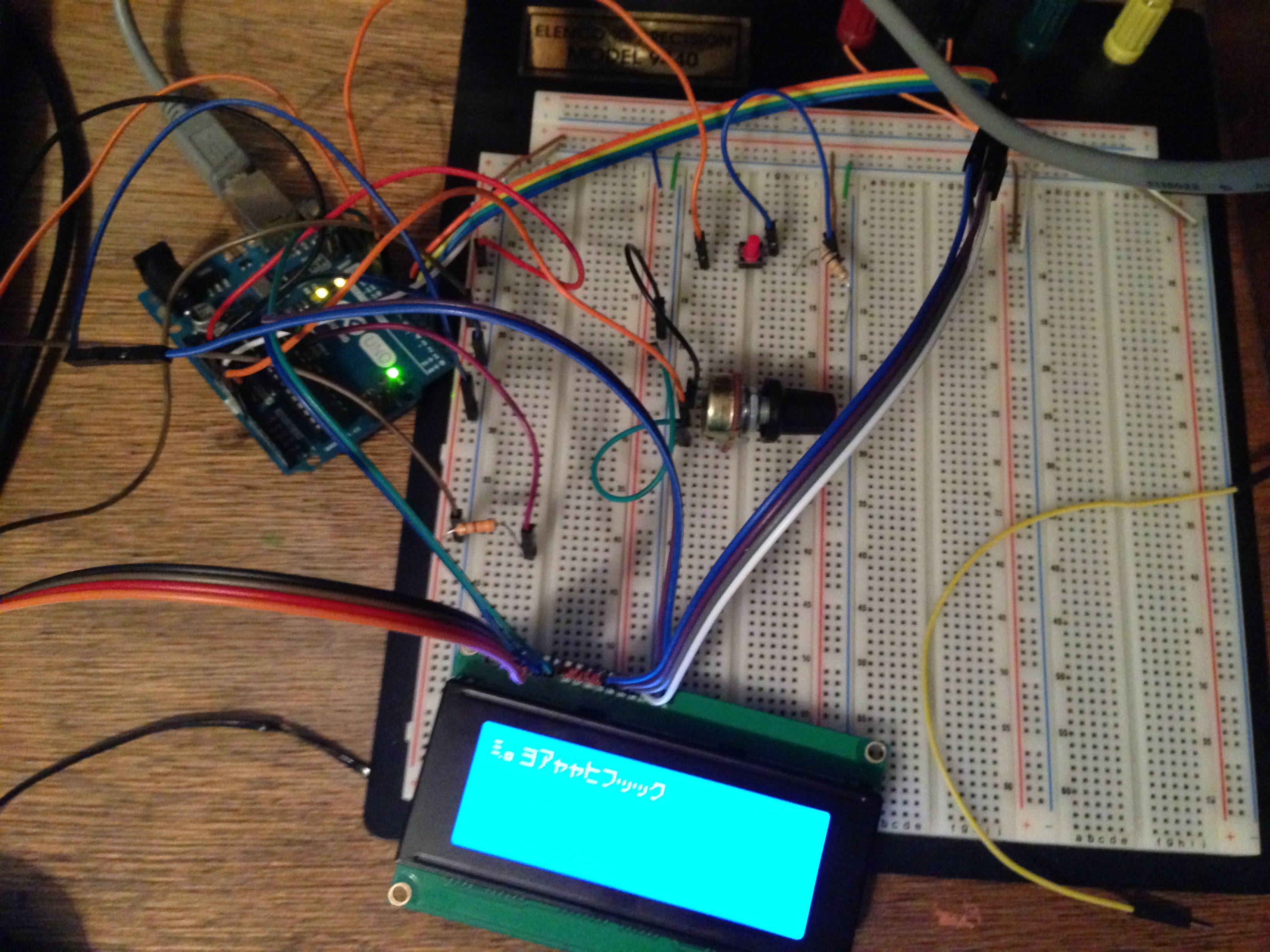
Looking at the datasheet for the Hitachi HD44780 LCD controller I learned that the character generator ROM has Japanese Katakana symbols. So I hooked up a quick test circuit and wrote out a bit of code, just so I could see the Katakana characters.
#include <LiquidCrystal.h>

int aval = 0;
int row = 0;
int col = 0;
char c = '0';

const int apin = A0;
const int button = 10;
const int rs = 12, en = 11, d4 = 5, d5 = 4, d6 = 3, d7 = 2;
LiquidCrystal lcd(rs, en, d4, d5, d6, d7);

void setup() {
  pinMode(button, INPUT);
  lcd.begin(20, 4);
  lcd.display();
  Serial.begin(9600);
}
void loop() {
  lcd.setCursor(col,row);
  aval = analogRead(apin);
  c = (aval % 64) + B10100000;
  lcd.print(c);
  Serial.print('\n');
  Serial.print(col);
  Serial.print('_');
  Serial.print(aval);
  Serial.print('_');
  Serial.println(aval, BIN);
  if (digitalRead(button) == HIGH){
    col++;
    if(col == 20){
      row = 1;
      col = 0;
    }
  }
   delay(200);
}
18 Jan 2020
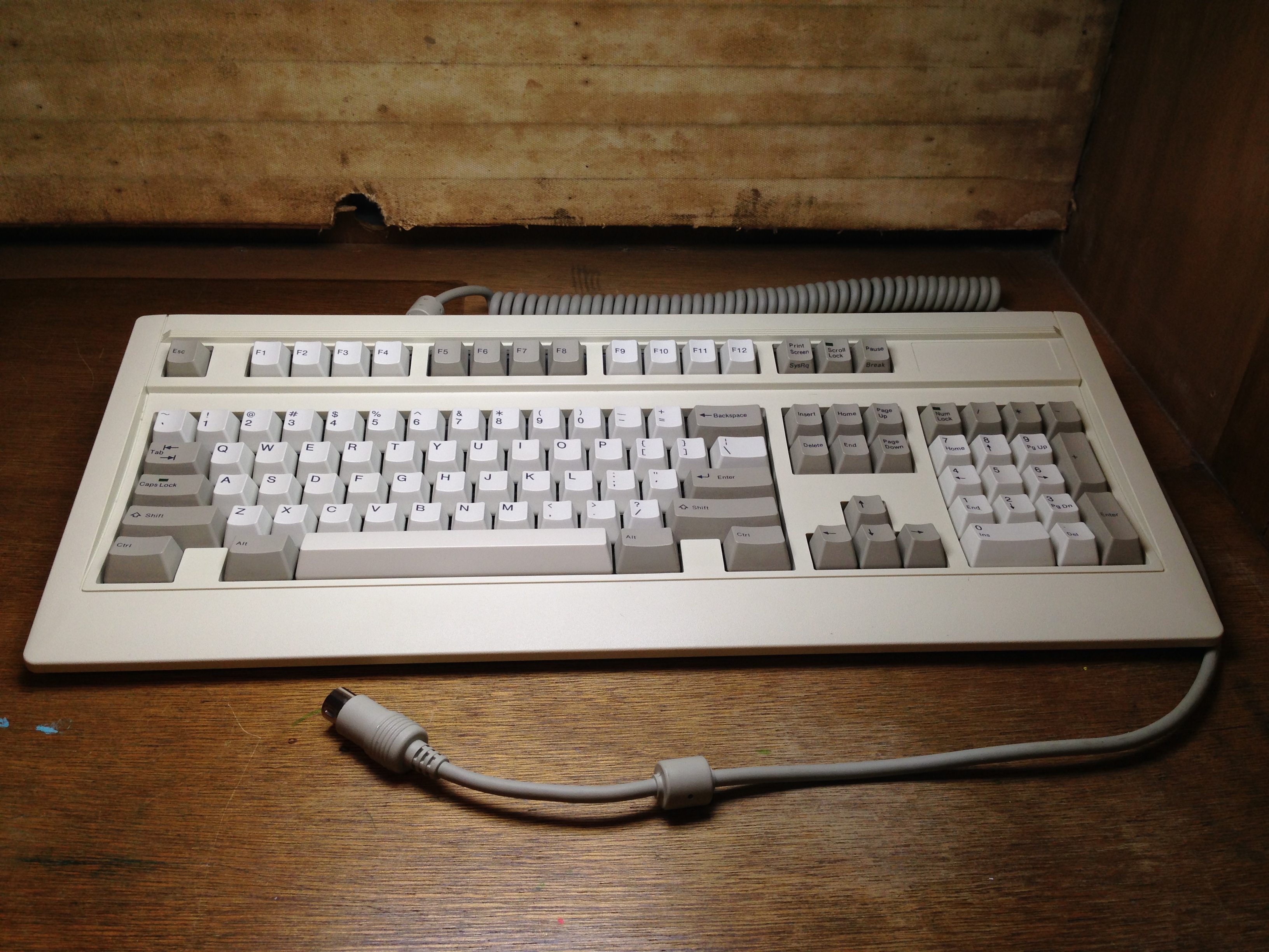
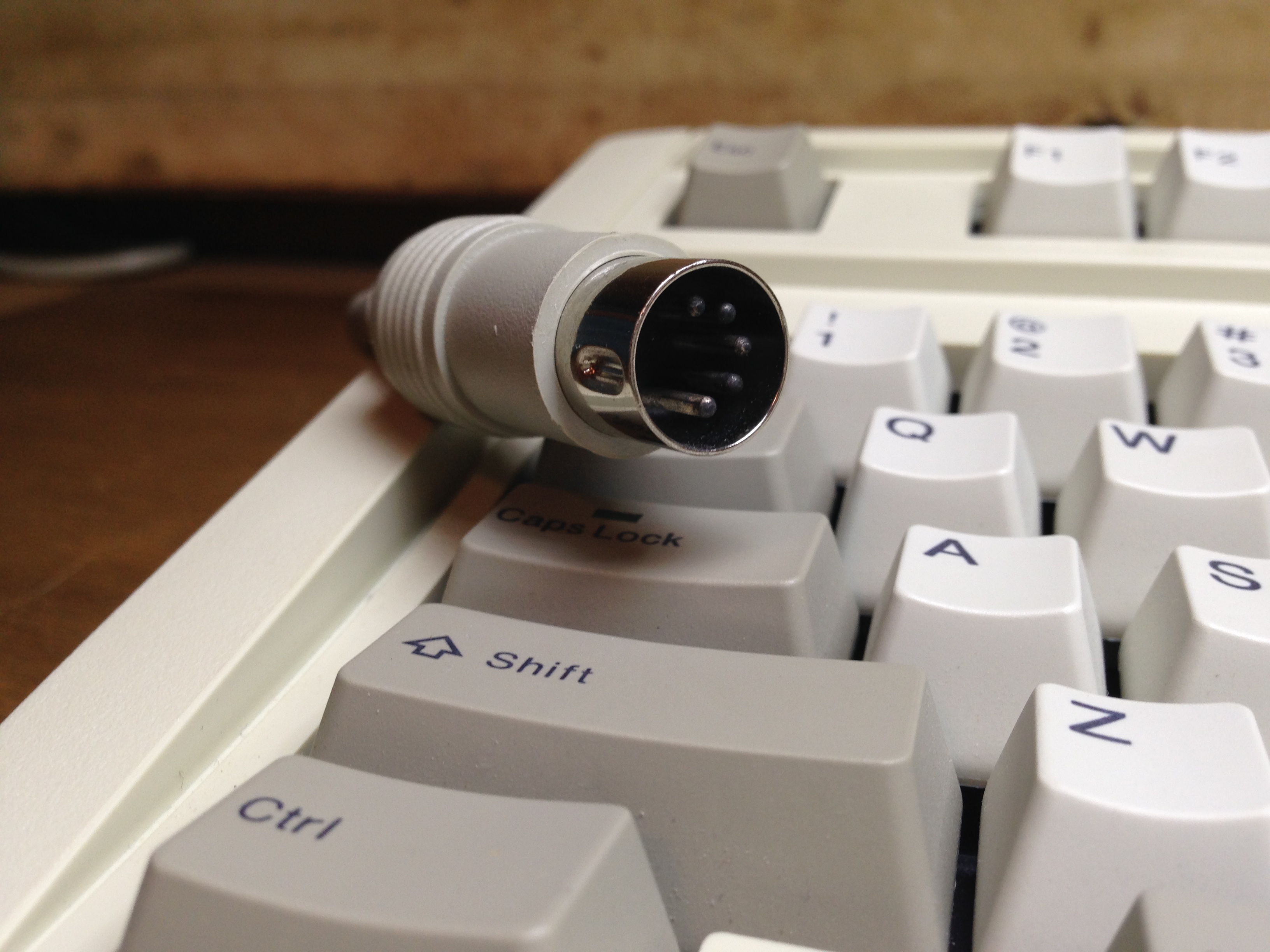
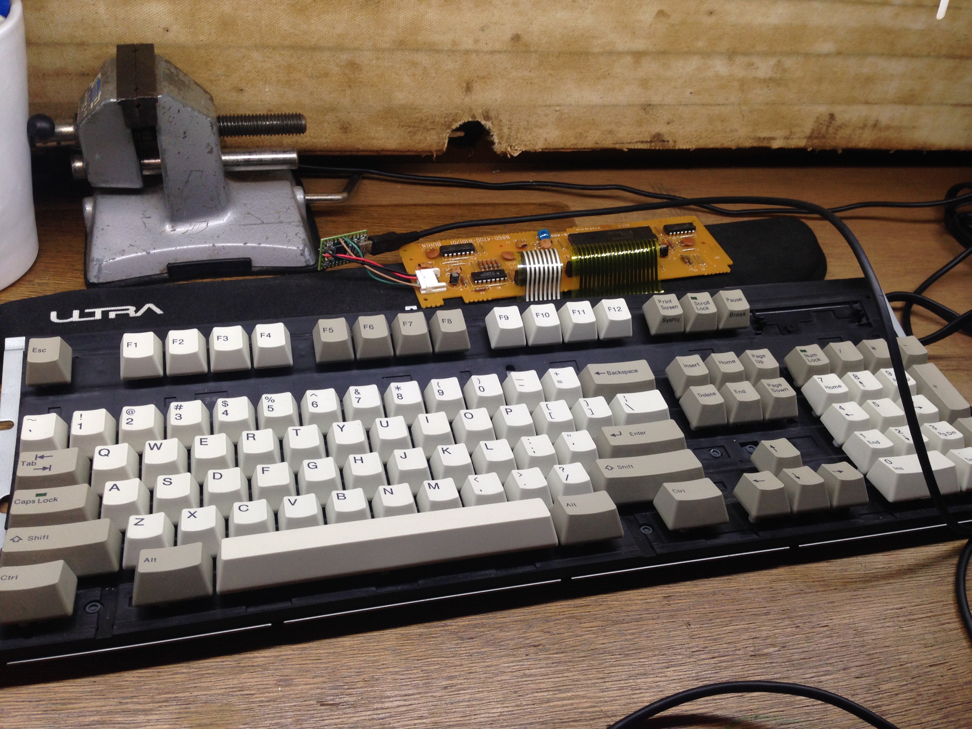
A few months ago I was looking through a thrift shop and found this 90’s keyboard with nice feeling switches. I bought it and planed on using it for my desktop computer. However, this keyboard uses the AT 5-pin DIN connector, so it is not as simple as buying a passive adapter and plugging everything together and calling it a day. This is how I made it work.
Parts List
To convert from the AT out of the keyboard to a USB input for a modern computer to understand, an active converter must be used. Thankfully others have done this before me. Soarer, a user on the deskthority and geekhack forums has posted code for a converter.
Using the Teensy Loader Application I loaded Soarer’s converter onto the Teensy.
Now to hook everything up!
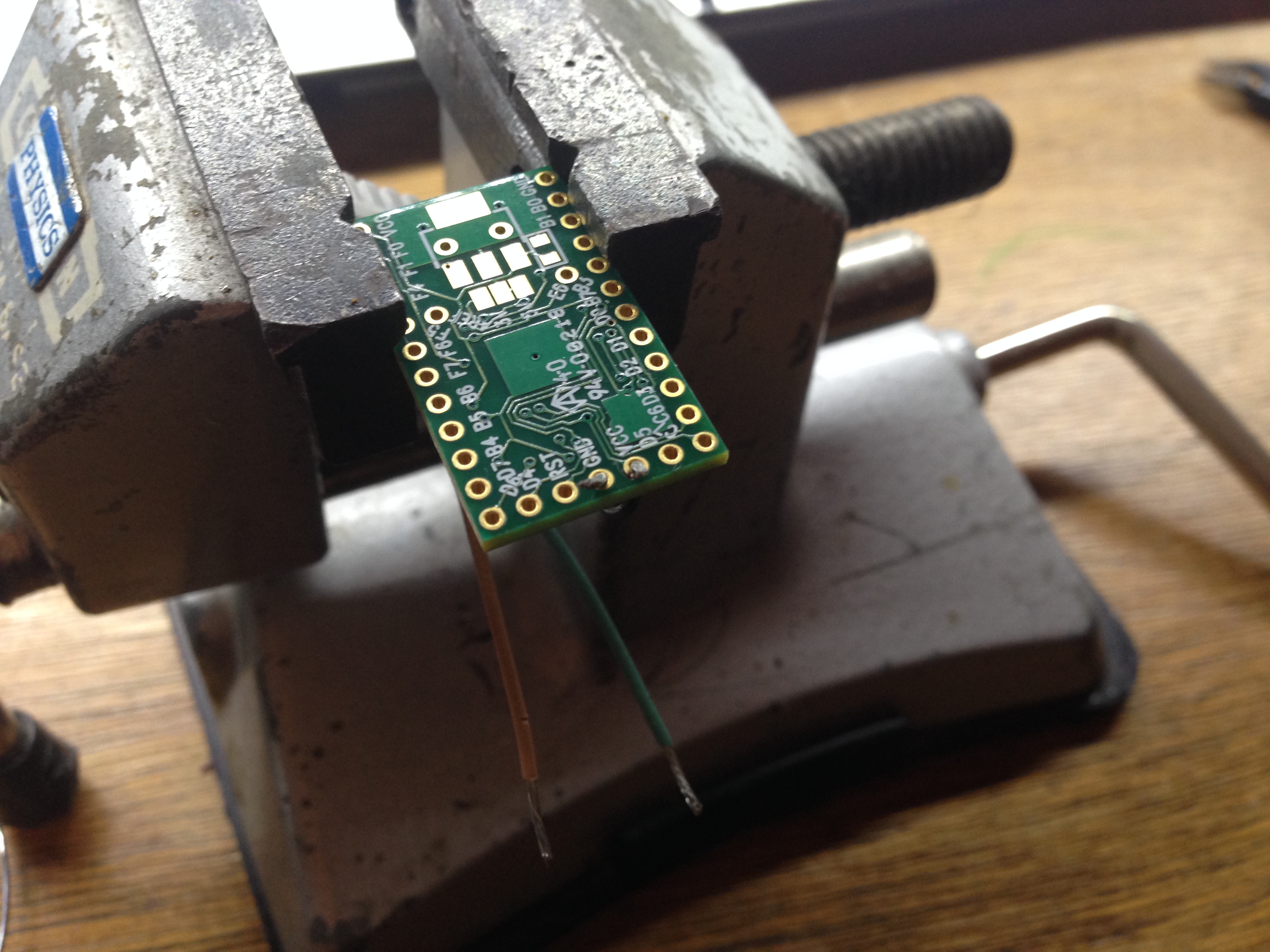
I disassembled the case, cut the AT cable, and stripped the wires back.
Then I soldered them like this:
| Keyboard OUT |
Teensy |
| GND |
GND |
| Vcc |
Vcc |
| Data |
D0 |
| Clock |
D1 |
Had to be extra careful because the colors were going against convention. Black was VCC and Red was GND in this cable. :/
To make the install cleaner I filed a square hole for my panel mount USB connector in the back, then reassembled the case.
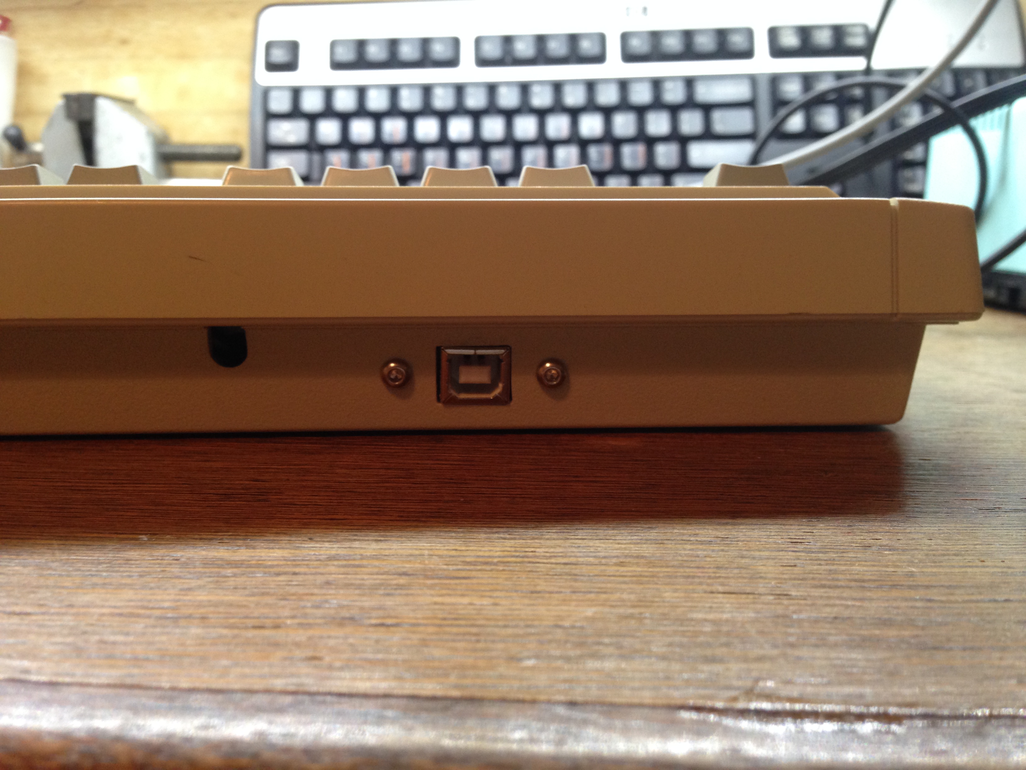
Finally plugged in to my computer, it worked perfectly! No bugs, no oddities, just plain works on my Linux machine and just plain works on Windows too. Even the LEDs in the caps/num/scroll locks work.
Yay!
22 Apr 2019
My good friend Karim Nasr and I worked on this together for an electronic class at Miami Dade College.
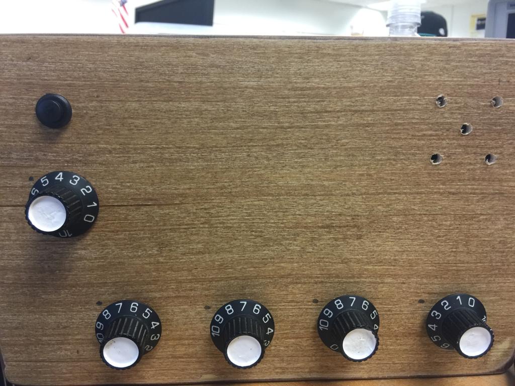
A music sequencer is device that plays back a pre-set sequence of sounds/notes/pitches/samples in an order set by the musician. This sequencer plays a series of four pitches each with the same duration. The tempo (the speed that the sequencer cycles) is determined by the top left potentiometer. Each of the four pitches are set by the four potentiometers along the bottom of the case.
This project’s purpose is to utilize the 555 timer IC in conjunction with a bilateral switch IC to get an input frequency from the Arduino UNO to cycle through 4 output frequencies that are modulated by potentiometers to change the pitch of the notes, thus creating a music sequencer.
Parts List
* [LM555 Timer](https://www.ti.com/lit/ds/symlink/lm555.pdf)
* Arduino UNO
* [CD4066 Quad Bilateral Switch](https://www.ti.com/lit/ds/symlink/cd4066b.pdf)
* 100 kOhm potentiometer x1
* 250 kOhm potentiometers x4
* 8 Ohm speaker ---
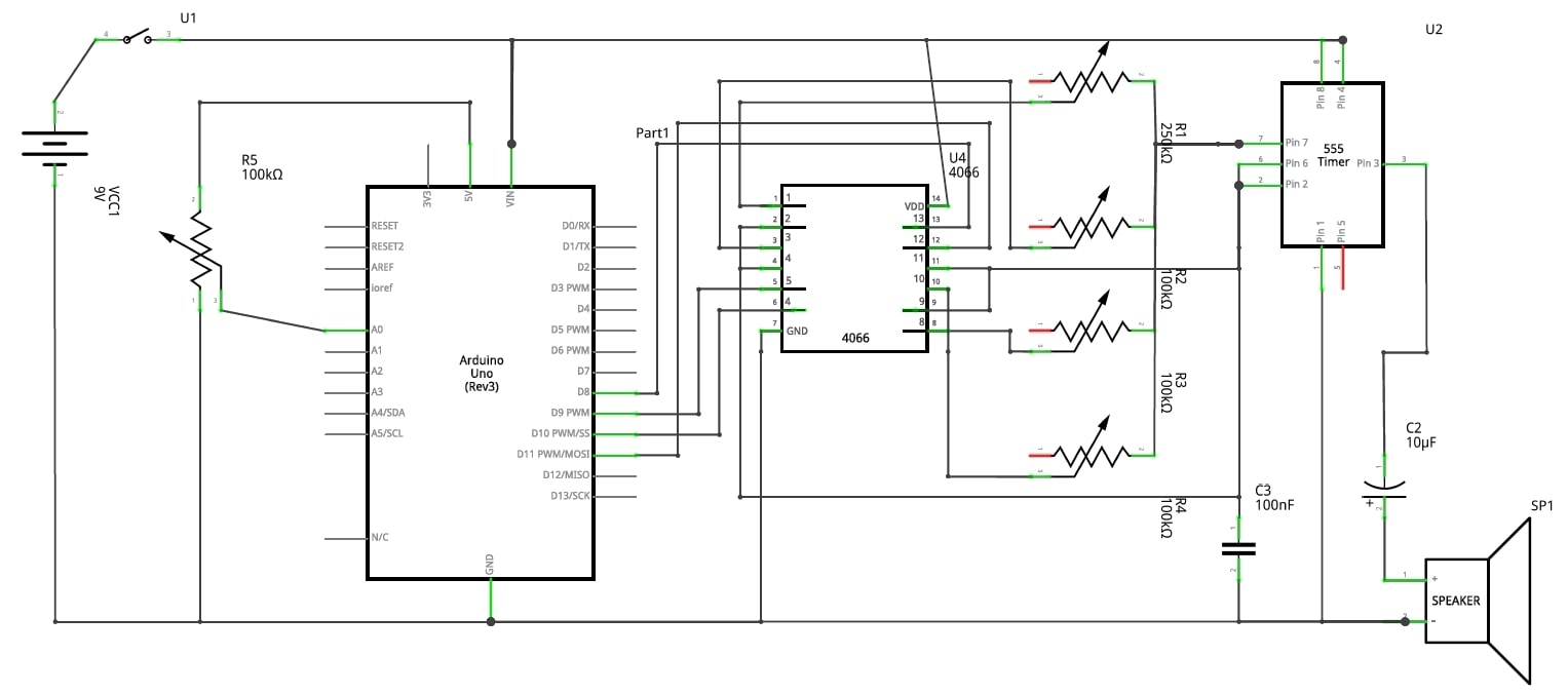 ^typo it should be R1=100k and R5=250k
Although there are digital elements in the sequencer, the sound generated is analog. Sound generation is handled by the 555 in astable operation. The frequency is set by the RC series circuit. If the 555 is the voice, then then the Arduino would be the brain.
    int sensorPin = A0;
    int ledPin = 13;
    int sensorValue = 0;
    int counter = 0;
    int A = 8;
    int B = 9;
    int C = 10;
    int D = 11;

    void setup() {
      pinMode(ledPin, OUTPUT);
      pinMode(A, OUTPUT);
      pinMode(B, OUTPUT);
      pinMode(C, OUTPUT);
      pinMode(D, OUTPUT);
       Serial.begin(9600);
    }

    void loop() {
      sensorValue = analogRead(sensorPin);
      Serial.print("\n sensor = ");
      Serial.print(sensorValue);
        Serial.print("\t counter = ");
      Serial.print(counter);

      switch(counter){
        case 0 :
        digitalWrite(A,HIGH);
        digitalWrite(B,LOW);
        digitalWrite(C,LOW);
        digitalWrite(D,LOW);
          break;
        case 1:
          digitalWrite(A,LOW);
          digitalWrite(B,HIGH);
          digitalWrite(C,LOW);
          digitalWrite(D,LOW);
          break;
          case 2:
          digitalWrite(A,LOW);
          digitalWrite(B,LOW);
          digitalWrite(C,HIGH);
          digitalWrite(D,LOW);
          break;
          case 3:
          digitalWrite(A,LOW);
          digitalWrite(B,LOW);
          digitalWrite(C,LOW);
          digitalWrite(D,HIGH);
          counter = -1;
          break;
      }
    counter++;
      delay(sensorValue);
    }
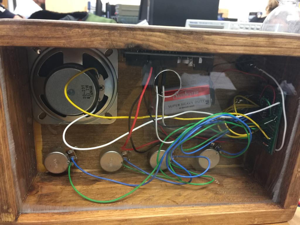
I made the case with reclaimed pallet wood, 1/4” plywood, and acrylic. It is fastened using dowels and a dado for the removable back.